Dmitrii Ryzhov, Ivan Pchelincev
Dec 25, 2020
Create a simple schematic and Arduino sketch with ESP8266 board and DS18B20 temperature sensor.
The Internet of Things is another area where you can apply the Abris Platform. With our tools, you can easily combine your Arduino-based projects (and other mcu) into a smart home network that allows you to store and process data in a user-friendly interface. We will show you how to save data using the ESP8266 and the temperature sensor (DS18B20). You must have the following tools: Docker, Arduino IDE.
First, you need to install the docker container image. To do this, run the following command in the command line prompt.
docker run -d -it -p 8081:80 -p 55432:5432 abrissite/abris-smarthome
This action will download an image from a remote repository and launch a container based on that image. Port 8081 is the port on which the web server will run and 55432 is the PostgreSQL database. You can set your own port values, but you need to make sure that the ports are not occupied by other applications.
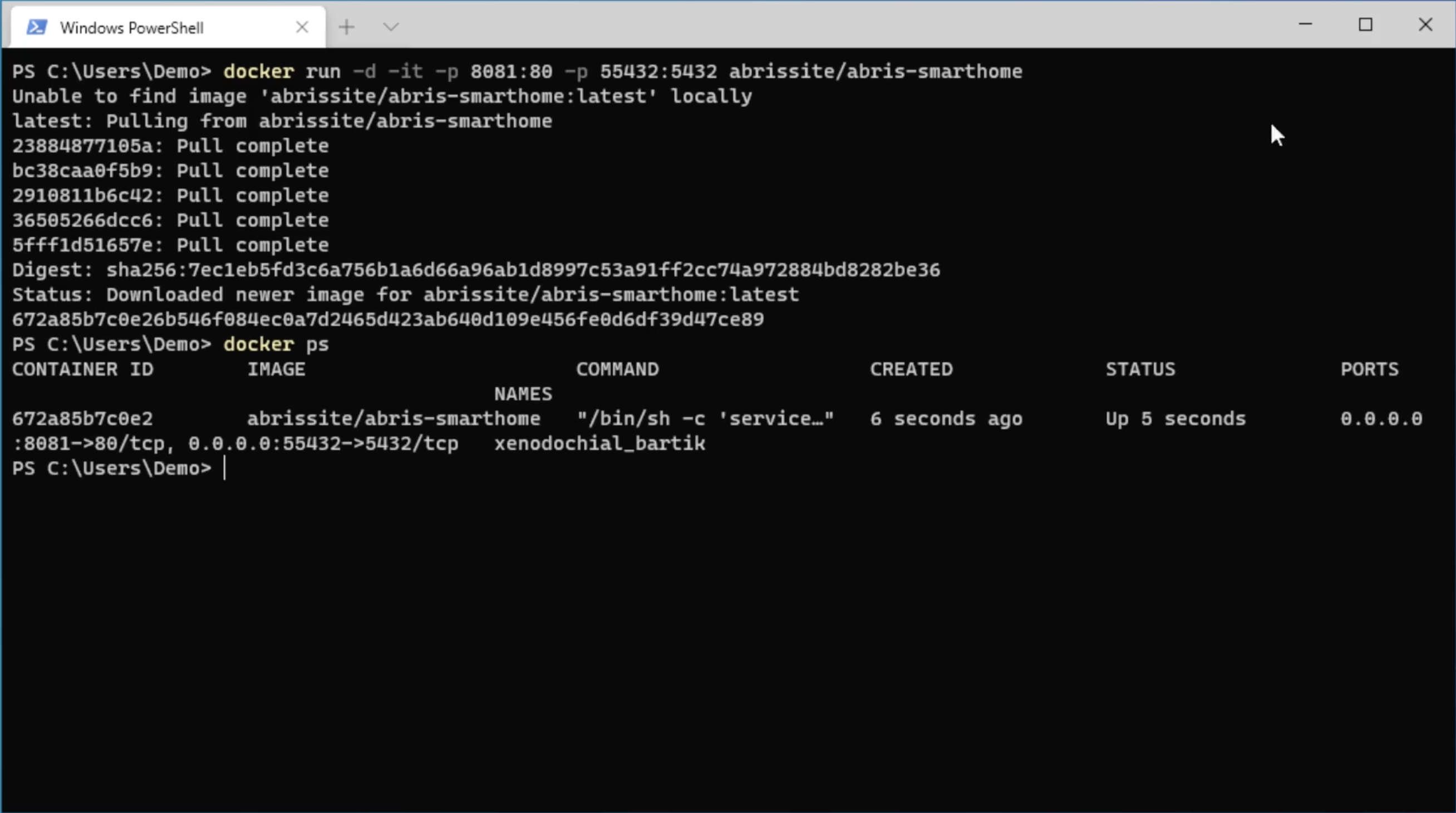
Аfter downloading, make sure that the container has started successfully. To do this, run the command.
docker ps
Result:
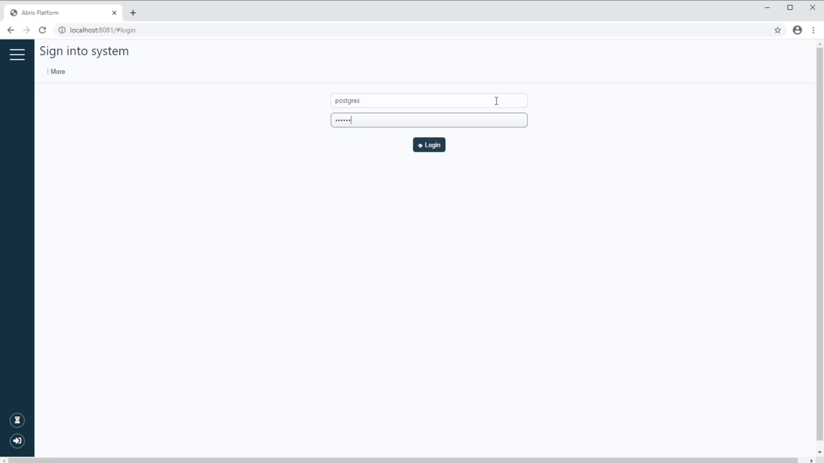
Next, open the web browser and go to the following address (the port is specified in the previous step). In the authorization form, fill the login (postgres) and password (123456) these values are set by default, click Login.
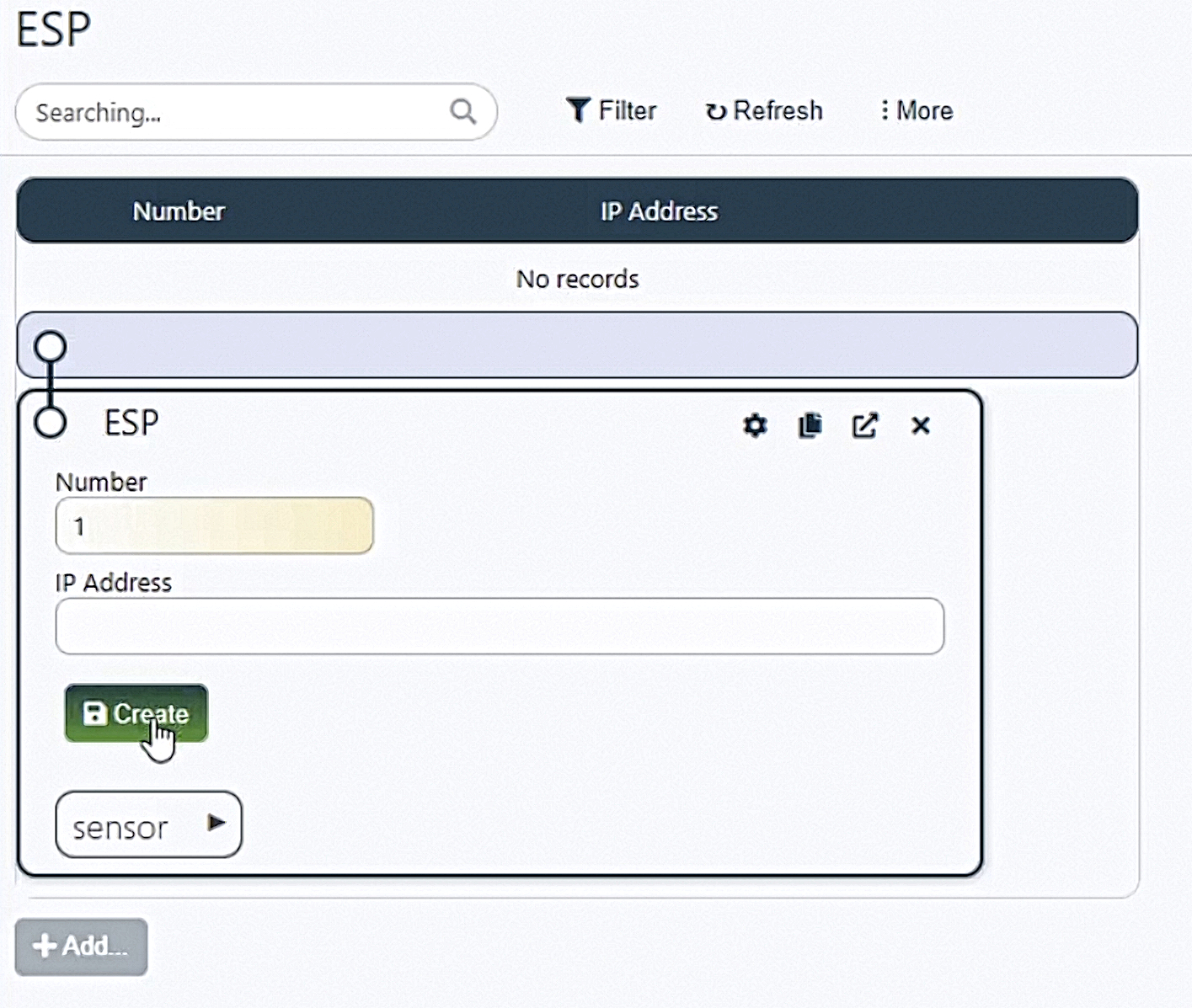
Next, you need to add a new sensor ESP to the system and the open form, fill the Number field with the value 1. At the moment, that is enough. Click the Save button.
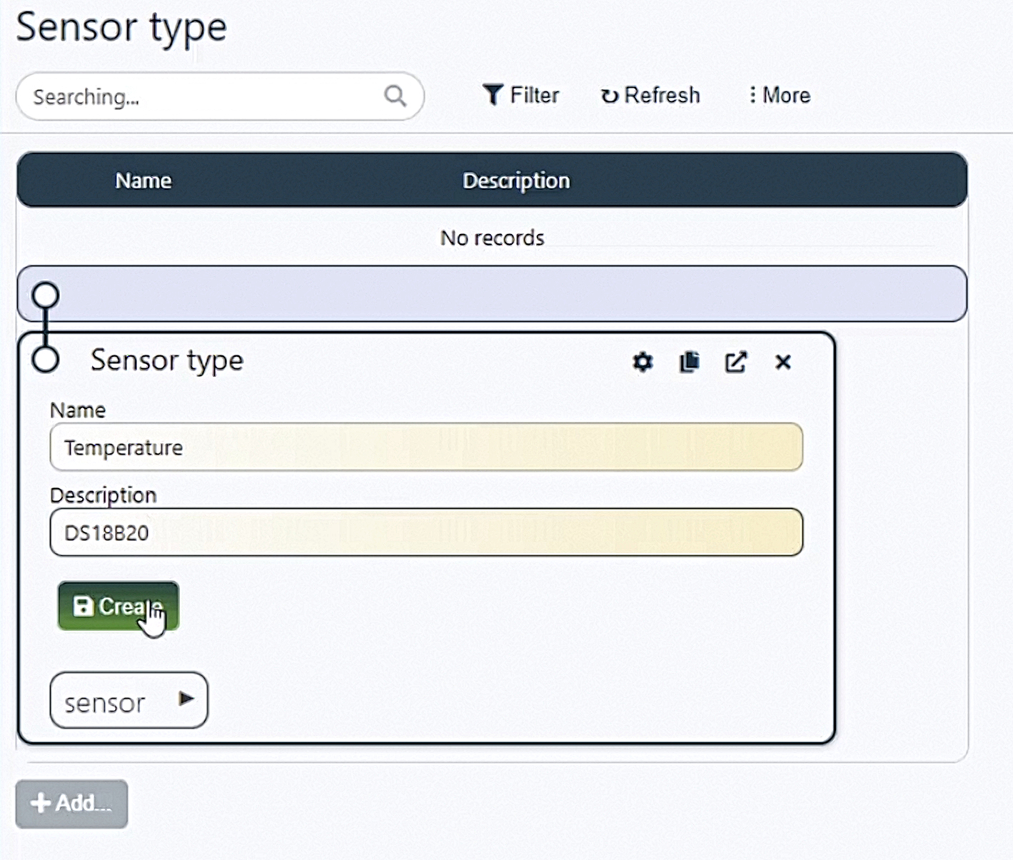
Next, create a new sensor type.
In the open form, add a new type called Temperature and the description of DS18B20.
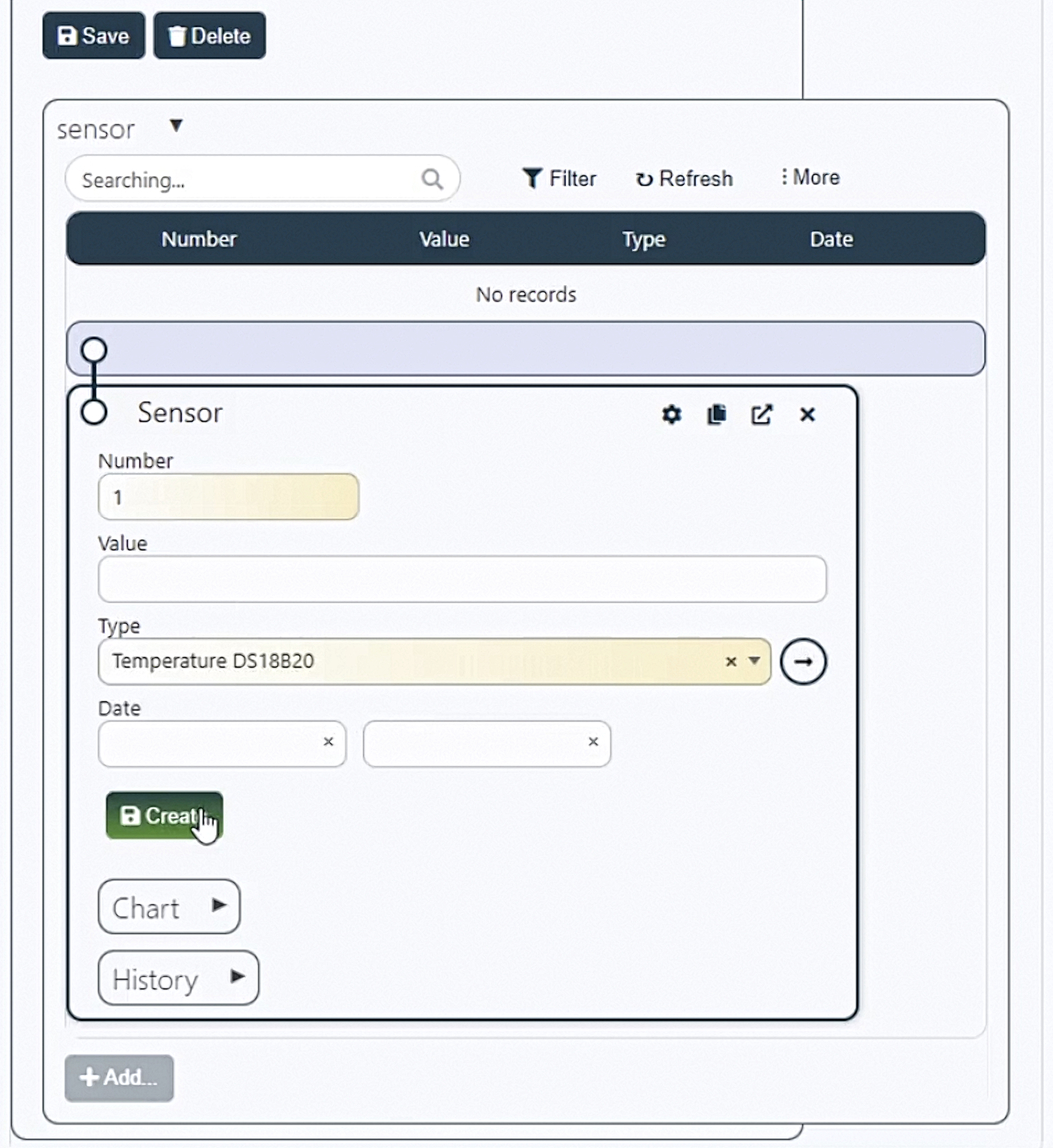
Go back to the table with devices and open the sensor table. Add a new sensor by assigning it a Number value of 1 and the previously createdTemperature type.
Next, the hardware part. This schematic shows the connection of the temperature sensor to the ESP8266 and it is necessary to connect a resistor between the ground and the power supply on the sensor.
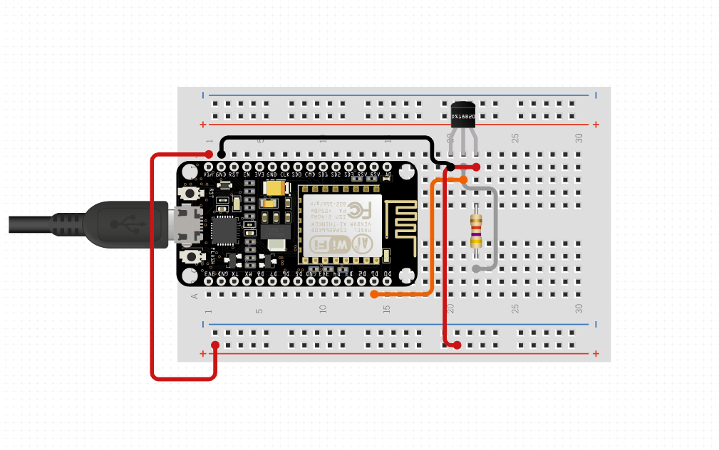
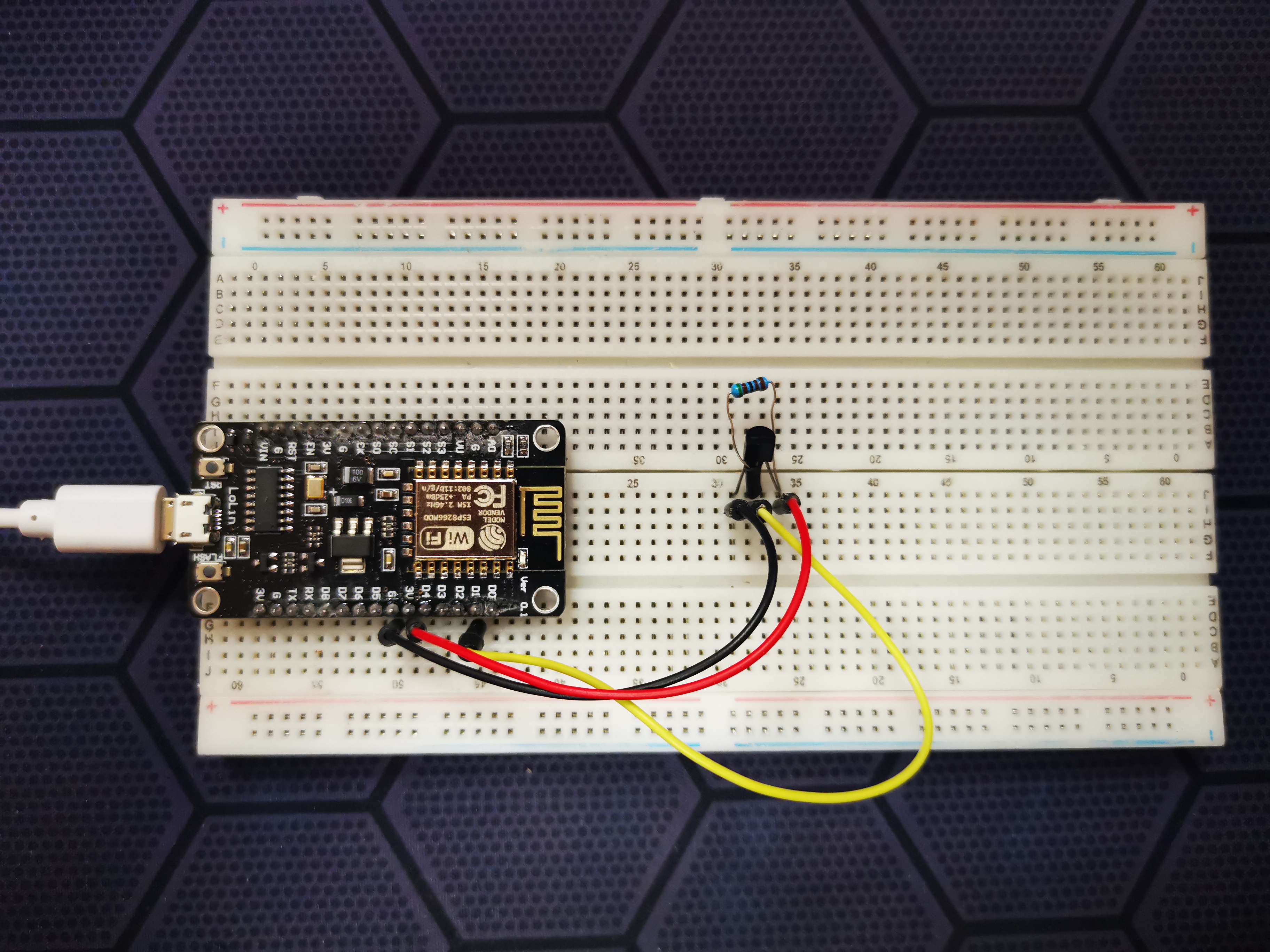
The model is built according to this schematic. You can get power by connecting the usb cable to your USB port.
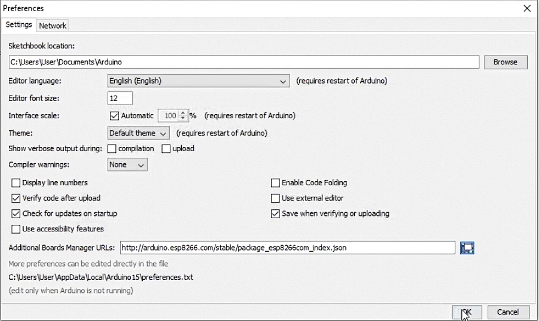
Open the development environment and create a new project. Go to the environment settings. Add the source for uploading the new board to the Arduino IDE by adding a link to the window.
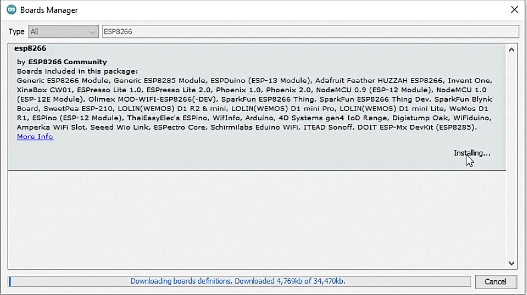
The next step is to install the board. Using the search, we find our ESP8266 board and perform the installation. When the installation is complete, click the Close button.
After installation, you need to select the current NodeMCU board - our ESP8266. After configuring the board, you need to download additional libraries (Abris Arduino, ArduinoJson, OneWire, Arduino Temperature Control). To do this, click the link from the description in the browser. Click the green Code button and click Download zip in the drop-down list. Repeat the previous actions for the other libraries.
Open the Arduino IDE and go to Sketch => Include Library => Add .Zip library and select the downloaded archive with the library. Press the button Choose. Repeat the previous actions for the other libraries.
Connect the ESP board and the temperature sensor to the USB port to the computer and in the development environment, select the software COM-port to which the model is connected. In the Examples select the example that comes with Abris Platform library.
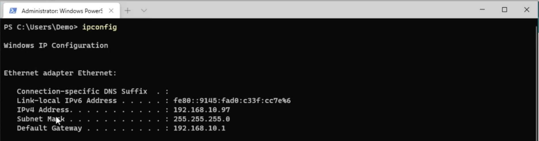
You need to configure the firmware. To do this, edit the following parameters in the open file: networkName of your WiFi network, networkPassword - for the wi-fi network, serverAddress - IP address of the computer running the docker container with the Abris.
const char * networkName = "WiFi";
const char * networkPassword = "123456";

const char * loginDB = "postgres";
const char * passwordDB = "123456";
const char * serverAddress = "192.168.0.1:8081";
You can view it using the ipconfig command (for Windows) and a command line prompt.
After entering the parameters, click the Upload button, which immediately checks the code and upload the firmware to the board.
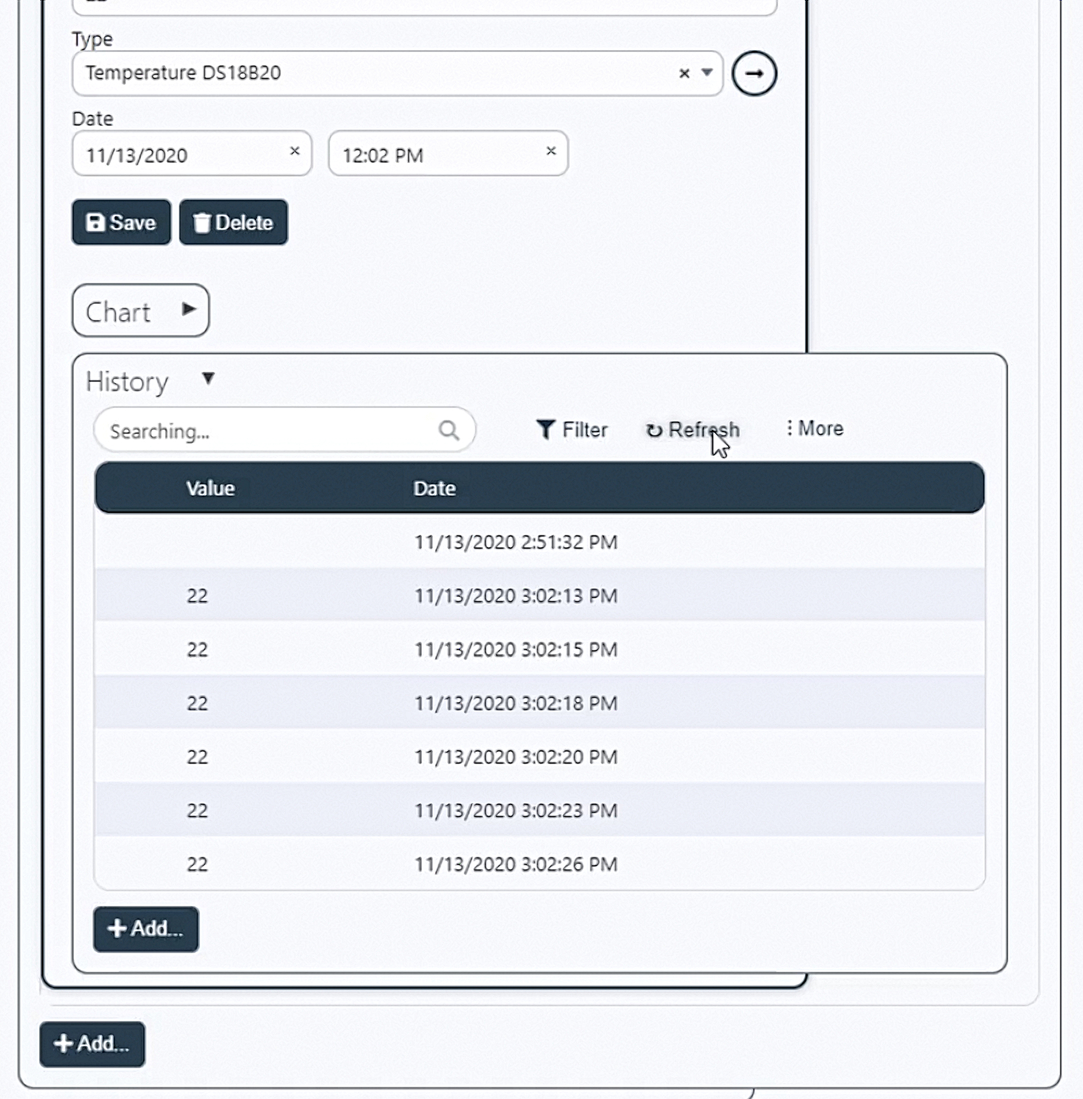
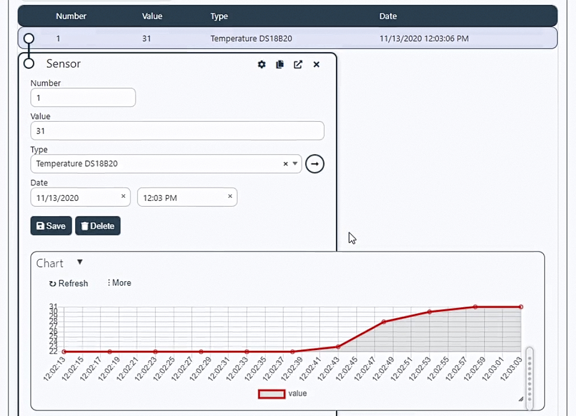
Go to the web browser and look at the values that come to the system from the board. As you can see, everything works without additional intervention, graphs are drawn, and the table is filled in.
For more information, see the video-instruction:
No code, no special design. Just install and use.
© 2020 Research laboratory ABRIS Ltd